Removal and installation of the A/B or C/912 fuel pumps is documented in the Porsche Workshop Manuals. Brief descriptions of the necessary steps are provided here. Other available sources should also be sought out for further description.
C/912 Pumps
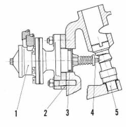
The steps required for removal of a C/912 pump is quite simple by disconnecting inlet and outlet hoses, removing attaching nuts, and then removing the pump (1) and insulating spacer (2). Installation is the reverse. There is no adjustment of the plunger spacing necessary during installation as this is determined internally to the pump itself.
A/B Pumps
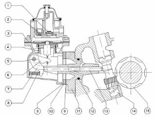
The steps to remove and install an A/B pump are a bit more involved because the spacing of the pump and flange will determine the working stroke and pump volume. Pages from the Porsche Worskshop Manual describing the steps can be downloaded from the link below. Installation of the fuel pump requires that the pump base be filled with grease, as this is the only lubrication provided to the bottom end of the pump.
CLICK HERE TO LINK TO THE WORKSHOP MANUAL ON A/B FUEL PUMPS
The Workshop Manual's Description of Stroke Adjustment:
1. Place intermediate flange, actuating rod, and a gasket, which should be in perfect condition, on crankcase. The oil hole in the intermediate flange must face upwards. The convex end of the actuating rod must face toward the cam of the distributor drive shaft.
2. Attach gauge VW 328a to the flange and tighten it to the same torque as for the fuel pump in order to compress the gaskets in their usual thickness. The actuating rod stroke of about 0.16" (4mm) is determined by the cam on the distributor drive shaft. The stroke should move to within a range of 2" (5mm) which is marked on the gauge. The marks correspond to a length of 1.14" (29mm) and 1.34" (34mm) measured from the fuel pump contact flange (including gaskets) to the projecting actuating rod end. Crank the engine to check the pump stroke. The specified stroke can be adjusted by fitting an appropriate number of gaskets to the intermediate flange. Do not fit less gaskets than required, as this would have a detrimental effect on the diaphragm and the drive mechanism.
***
A Practical Translation (i.e.an easy How-To):
The steps described in the manual involve the use of a special VW 328a tool, which is not too common anymore. But the stroke adjustment can be quite easily carried out without this tool. The description above explains that the 4mm actuating stroke needs to be within a 5mm range of 29-34mm, as measured from the flange surface (including compressed gaskets) to the rod end. The location of this surface can be determined by using washers and nuts to hold and compress the flange and gaskets in place. Measure the stroke from this location to the rod end through two complete engine rotations. Add (or subtract) gaskets as needed. It will be safest to keep this stroke length below 33mm through the addition of gaskets. This resulting working stroke should be less than the actuating stroke, where 2-3mm is sufficient. It is more likely than not that the addition of one gasket (for a total of three) will provide the necessary safe separation for a working stroke within this range.